FMP and Thesis Proposal

FMP_Immersive game

GAME OVERVIEW

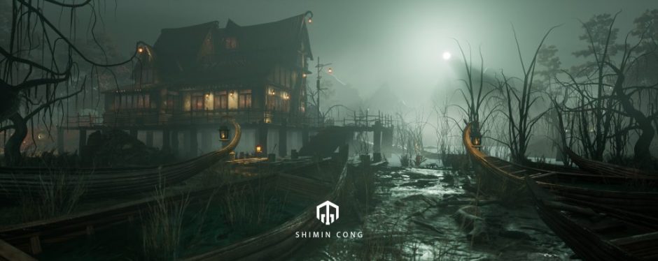
This project is a demo of a horror puzzle game with a play time of 5-10 minutes. Players will listen to a memory of the protagonist in a short game time. The focus of game design is on immersive experience. This includes the stylized model of the game scene, lighting, layout and UI…

WHY CREATE THIS GAME?

In addition to the innovation in gameplay, many gamers are beginning to pay more and more attention to the visual effects of the game。

In the second and third term game project and the production of Cthulhu CG animation, I have mastered the Unreal material system, lighting system, VFX system, sequence frame system and terrain system. But to become a game technical artist, I also need to start a game project to consolidate the skills learned while mastering the ability to write blueprint logic.

In addition, besides technical art, my second job choice is game terrain editor. Therefore, the game project is still based on the scene experience. Taking into account the limitation of playable time, in order to make players have a good sense of game immersion, thriller is a good direction.

Finally, I also hope to consolidate the knowledge of story arc through this project, and enhance my storytelling ability.

RESEARCH AREAS

  • Game level design
  • story arc
  • Interaction design_ flow experience and unconscious design
  • Unreal
    • Blueprint
    • VFX system
    • Material system
    • Lighting system
    • terrain system
    • Engine logic

REFERENCES

Chen Xinghan believes that games should not be regarded as products that promote violence. The flow experience of games should be pleasant and satisfying. Through the research of flow experience, he has produced many well-known art games, such as Journey “, “flower”, etc.

As for the game’s biggest reference, Edith Finch is the game. One of its major features is that the subtitles are cleverly integrated into the scene. And this form of storytelling is also worthy of reference.

In contrast, the interactive design of plants and fish in ZBZU’s game is worth studying. With such a large scene, it is obvious that the movements of these fish are not done through traditional rig and animation, but through the world scene position offset and mask to control.

AIM

  • Perceived immersion
    Complete perceptual experience- more perceptual experience the game can provide
    Strong emotional response-the game can arouse strong emotional ups and downs in the player
    Emotional interaction and resonance-the game experience can arouse the player’s emotional resonance
    That is to have a perfect game scene, scene layout and lighting
  • Cognitive immersion
    Cognitive immersion includes three aspects. Keep cognition as simple as possible, use visual levels to sort out information, and use narrative design methods to make players more immersed. That is to have a complete and ups and downs story line.
  • Operational immersion
    At the operational level, if you want players to form a sense of immersion, you must have a reasonable UI layout and icon design.
  • Improve the skills required by game technical artists.

RESOURCES TO USE

  • MAYA _modeling character rigging and simple animating
  • RizomUV_ Onwrapping
  • Mari_character color map and displacement map
  • Mixer_ texturing for landscape and wall
  • Substance painter and designer_ texturing for object
  • Zbrush_Sculpturing
  • Houdini_ landscape system
  • Unreal4

Thesis Proposal

My thesis is related to the FMP project. They are all aimed at the immersive experience of games. And thesis is to analyze immersive games in the field of flow experience and unconscious design. FMP is a practical study of the thesis.

Abstract

Flow experience, unconscious design and immersion are the words we often mention in game development. An immersive game is more than just a beautiful game scene. It also needs to cooperate with the gameplay mechanism, UI, story and other factors. Therefore, this article will specifically introduce the concepts of flow experience, unconscious design and immersion, as well as the previous relationship between the three.

Flow experience

The creator of flow theory is Mihari, a famous American psychologist. He initially discovered this shared experience-flow experience through a large number of interviews by studying the source of people’s happiness. There are eight characteristic elements that constitute the flow experience, including: 1 clear goal, 2 timely feedback, 3 challenge and ability balance, 4 sense of control, 5 elimination of distracting thoughts, 6 concentration of current tasks, 7 loss of self-awareness, 8 sense of time distort.
Analyze the practical application of the flow experience of “flower” and “ABZU”. (Gameplay mechanism and game scene construction)

Unconscious design

Unconscious design is the designer’s unconscious operation through conscious design. This article will specifically describe how the game UI design enhances immersion from the unconscious aspect.

Reference

https://en.wikipedia.org/wiki/Flow_(psychology)

https://www.frontiersin.org/articles/10.3389/fpsyg.2020.00158/full

Hoshi, K. and Waterworth, J., 2020. Unconscious Interaction and Design. In Primitive Interaction Design (pp. 75-86). Springer, Cham.
Posted in FMP and Thesis | Leave a comment

Term2: Houdini course_6

This week I learned and made the dissipation effects, the particles follow the smoke, and the model damage effects. Obviously, these effects require a lot of computer calculations. A long part of the learning process is spent waiting for calculations. The following is an introduction to the learning process of the three effects.

Test 1

The test is to make an object dissipate. The first stage of dissipate is the same as the first stage of object damage where the voronoi is needed to divide the object into multiple small fragments. The nodes in the figure below are nodes inside the DOP, which are used to detect the physical properties of the model. But the test result is that there is no gravity.

Torus did not move after adding gravity. It is because the model is not packed.

The solution is to add an assemble node and check the Create Packed Geometry command. The following is the display effect:

Next is the production of Torus’s dissipation effect from left to right. First of all, let me introduce some nodes:

In the DOPnet node rigidbodysolver includes bulletrbdsolver.

Multisolver can combine multiple different types of solvers to work together.

Create an active group and static group before making a left-to-right dissipation effect. Adding! before STATIC group!, Represents all parts except STATIC group. The display effect is as follows:

另一种分组方式,如图所示,我们可以通过noise来将point赋予0和1的值。其中1代表actice group。

Another way of grouping, as shown in the figure, we can assign points to values of 0 and 1 through noise. Where 1 represents actice group.

It can be seen from the above figure that the model is dissipating in the white area of the particle.

The purpose of the Fit, add, clamp and floatpoint node is to change all the points to 0 and 1. And expose the parameters of the add node, which can make all the points switch back and forth between 0 and 1, and make animations.

The following is the dissipation effect after set the frame.

The next step is to gradually reduce the dissipated small pieces, so an SOP solver needs to be added.

inside of sopsolver

The role of Attribpromote is to create a prim attribute. The role of primitive is to narrow the selected group.

The final step is to hide the smaller particles.

When the value of the tokeep attribute is less than 0.1, the fragments will disappear automatically.

So far, the effect of dissipating objects has been completed. We can replace some other objects. The following is what I replaced with a monster model I made before.

Test2

The second test is to make a particle follow the smoke effect. The first is to make a smoke.

To make it easier to observe, we can create two lights to illuminate the smoke.

The following is the display effect of smoke.

Before creating the particles, we need to simulate the smoke first.

The role of the popadvectbyvolume node is to let particles follow volume.

The following is the display effect of particle.

After that, we need to convert the particles to sphere so that the particles can be rendered. The required node is copytopoint. The following is the display effect of the final result.

Test3

The last test is to make an effect that the meteorite explodes after hitting the building. But because only half of the work was made this week.

After getting the model, we need to clean up the model.

Introduction to clean model nodes:

  • fuse: This node is often used to process and merge adjacent points.
  • divide: The remove shared edges command of this node is used to delete shared edges, and it can also detect whether the model needs to be cleaned up.
  • facet: In order to solve the point after dissolving the broken tuning, you need to use the remove innline point command in this node.
  • polyfill: automatically fill the hole.
  • .clean: The fix overlap command can repair the overlapped part
  • boolean: Union command can melt the overlapping part.

Model reduction polyreduce This node can quickly convert high polygon to low polygon, but sometimes the model will be damaged and the shape will be broken.

Another reduceface method is the combination of vdbfromepolygons and convertvdb. We can get a cleaned model and the shape is more accurate.

The third method of reduceface is the project model. Which needs to use the ray node, and need to create a sphere polygon. Need to pay attention to the connection method of the node port as shown in the figure above.

The role of extracttransform is to transfer the motion of one model to another. Inport01 is the information of the first key frame entered, and inport02 is the complete animation information. At the same time, the copy to point node is needed to link the model to be moved and the output animation information.

The role of pointdeform is also to assign the movement of one model to another model.

After the model is cleaned up, we need to pre-process the broken effect:

Test the simulation. If the normal is created in this way, each layer of the building will be split in the same way. This effect is not what we want.

The solution is as shown in the node link. The role of connectivity is to create a class attribute, and the role of the nodes in the yellow area is to divide the model into different groups. In this way, the fragmentation of voronoi between different groups will be different.

Later, I grouped buliding into different materials.

The role of normal is to adjust the smoothness of the model.

Broken problem: In the pre-processing voronoi effect, such a phenomenon of model damage often occurs.

This is a very time-consuming process, we need to adjust the data on the right side of the above figure to test. In addition, in order to facilitate the simulation, we can separate the groups with issues and adjust them separately.

At this point, this week’s practice department is over. In the process of learning, I always encounter some new nodes and forget the old ones. But the production itself is a good way to consolidate and review.

Posted in Term 2-Advanced techniques | Leave a comment

Term2: Houdini course_5

This week I mainly reviewed the modeling function of Houdini. In addition, I also learned and made Arnold rendering and some simple fire smoke, flame and explosion special effects.In general, this week’s knowledge points will be more difficult than the previous 4 weeks. Because this involves many new nodes.

Modeling

First, I made a tunnel by myself based on tutor’s video.

During the environment material creation process, replace the ouput node with the out_environment node.

In the lighting phase, it is important to note that the distance and hdr maps cannot identify volumetric fog.

The noise node makes the fog effect more realistic.

Smoke

smoke node display
inside of dop

Lighting disappeared after adding gasturbulance node.

We can go back to the geometry level and select the dopnet node, and then click the icon at the red mark. In this way, we can watch the results of lighting while adjusting the internal nodes of dopnet.

The first difference between the old solver and the new solver is that the boundary of the old solver is fixed and needs to be adjusted manually. In addition, the division size should be the same value as the voxel size in the volumeterasterizeattributes node.

The second difference between the old solver and the new solver: Under the same force field and the same number of frames, it is obvious that the bound of the latter will be larger. there is also a lot of empty voxels and these voxels are just ignored by the by the simulation.

The above is a demonstration of making the smoke effect.

Fire

Pyrosolver is aimed at fire effects, which includes the function of smoke effects.

Saving simulation vdb is open vdb, which is an updated general volume data type. It can export vdb format as general material. This contains a variety of density and volume data, which is a larger collection of data than fog, SDF, etc.

The above is a demonstration of the completion of fire effect production

In the texturing phase, what we want to create is the material node for smoke-standard _volume.

Controlling Emission through channel.

The next test is: adding a physical collision to the sphere, which can affect the shape of the fire. The effect is shown in the figure below:

Obviously, we can observe the flame being passed through. But such collisions are not real. The real flame collision should also have the effect of the flame being affected by the wind, in the direction of movement of the sphere.

In response, the following adjustments have been made.

We added a pointvelocity node which is used to increase the V attribute.The results are as follows:

Explosion

explosion node display

Emission can be adjusted here. The following is a comparison of the effects before and after adjustment.

Above is a preview of the flame effect.

Before rendering, we must convert the explosion to VDB so that the effect of the explosion can be simulated.

But after the texturing is over, the rendering results are as shown in the figure above. Obviously there was an error in my production process.

After many inspections of normals: the white effect is due to the rendering of redundant objects. As shown in the figure above: the white effect is due to the simultaneous rendering of two objects, explosion and Arnold_volume. Obviously we only need to keep the Arnold volume.

The above is the explosion effect after adjusting the material.

The last test of the week is to add a physical collision to the explosion. The shape of the smoke after the explosion is affected by the collision with the sphere.The figure above is the connection of nodes.

The above is the effect before and after the physical collision is increased.

Posted in Term 2-Advanced techniques | Leave a comment

Team project summarize

Nine weeks may seem like a long time, but if you want to do a good project, these events are not enough. I really enjoy this inter-professional collaboration project. In this process, I learned the production process of a game project for the first time, and learned some material nodes of Unreal and substance designer from Chris. I also like to teach my model making process to my team members. Unfortunately, due to the limited number of people, the project could not be completed within 9 weeks, but the project will continue and strive to be completed before graduation. At the same time, I will also record the subsequent production process in the Blog.

In the later stage of the project, I hope to share some knowledge about code with team members, which will help to develop in the direction of technical artists.

Posted in Collaboration | Leave a comment

Week9:Grass modeling and some test in Unreal

In the production of the last week, the characters I was in charge were the production of grass models and textures. And write the material shader in Unreal.

Color map

First, I drew some grass leaves in photoshop based on the 2D concept.

Modeling in MAYA

Testing in Unreal

As shown in the figure, you can find that the roots of the grass model are too concentrated at one point. , And the whole is trivial. , I tried new models and textures for this.

This grass looks more cartoonish and uniform. The next step is to add motion effects to the grass.

Rock material shader test

Posted in Collaboration | Leave a comment

Week8:Unwrapping and Texturing for car and rock

In the eighth week of work, my main task is Unwarping and Texturing in Rizom UV and Substance painter. Before Unwarping for car, the most important process was to divide shaders.

Car

As shown in the picture, I divided the car into 8 parts, namely 8 UVs.

After Unwarping is over, it is the Texturing phase. As shown in the picture is my production process in substance painter. The rendering effect of Vray is as follows:

Finally rendering in MAYA,testing maps .

Rocks

Unwarping in RizomUV

Make lighting UV in MAYA

Since my game project requires lighting and baking, lightingUV is essential. Although the second set of UVs is automatically generated when the model is imported into Unreal, such UVs are sometimes not easy to use.

You can copy a new UV at the position shown in the figure, and scale the UV slightly to make the two UVs slightly different.

Texturing in substance painter

Since the model is low poly, we need to get high poly Normal and AO in Zbrush. If this is not the case, the visual effect of high polygon will not be obtained.

However, due to the modification of the model, the problem as shown in the figure will be encountered.

Fixing the normal map in photoshop

Then texturing in Substance painter

Posted in Collaboration | Leave a comment

Week7:Modeling car and Substance designer test

In the seventh week, my main job was modeling a car which was gaven by my tutor. The main reasons why I accepted this project like modeling and want to participate in foreign commercial projects.

This is a challenge. Before that, I didn’t know much about the structure of the car. Especially if the reference picture is very vague.

In this regard, I found many similar models on the Internet as a reference to understand the structure of the car.

In the process of modeling, always pay attention to the number of control triangles, because this is an unknown project. I hope my model can be used in any project.

The following is the process diagram of the model:

During the modeling process, I often press 1 and 3 to observe the harden edge and soft edge modes of the model.

The following figure shows Harden edge mode and soft edge mode after the model is completed:

harden edge
soft edge

Substance designer test

There are two options for the landscape part of my game project:

1. Manually place the model including a large area of ground

2. Programmatically generated terrain (world creator or substance designer, or houdini) I currently have a preliminary grasp of Worldcreator. The advantage of this software is that it can be quickly learned and used, but the methods for generating special terrain are limited. But this week I mainly want to try Substance designer to generate terrain.

Then,export the map to Unreal

The final result is similar to worldcreator. But for special terrain, substance designer needs to study more deeply. For the seabed terrain in my project, after another discussion by the team, it was decided that there is no need for complicated procedural node generation. The existing rock model can support the required scene.

In other words, such terrain cannot be used well in the project.

In addition, I also tried the production of rock material in substance designer.

Posted in Collaboration | Leave a comment

Week6:Modeling and Topology

My main work this week is the remaining work of the rock last week and Topology the highpoly rock. Since it is a game project, there is a limit to the number of triangles in the model. This must ensure the normal operation of the game. After negotiating with Chris, it was finally decided that the average number of faces of each rock should be less than 2000 triangle faces.

2000 triangle faces are simple for a small rock, but for some large models, a lot of details will be lost, despite the support of basecolor map, normal map, roughness map and AO.

Modeling

The following picture is this week’s rock and crystal sculpturing in Zbrush:

Topology

In Zbrush, Decimation Master is a powerful face reduction tool. We can reduce the number of high polygon faces through this plug-in.

The following is the comparison before and after Decimating face:

After all the stones have been processed, all models are imported into Maya, and the model is manually repaired for the second time.

如图所示,经过长时间修补,所有模型的三角面总和低于5万。

Posted in Collaboration | Leave a comment

Week5:Modeling in Zbrush

The main goal this week is to complete the carving of the rock model. A total of 35 rocks are included. The polish of the rock carving is crucial. It takes a lot of time to deal with edges and cracks. Because these details directly affect the large-area picture effect in the scene. Therefore, I will continue to sculpt the rock in Zbrush until the next group discussion begins.

In this process, I successfully mastered the skills of using the new brush. The following is my experience during the engraving demonstration.

Brush

These are the 3 most commonly used brushes for sculpting rocks. The first two brushes are mainly used for polish. The last brush is used to create cracks. The following are the recommended masks for the first two brushes:

Here are the rocks that were carved this week:

Posted in Collaboration | Leave a comment

Term2: Lighting course_2

The main content of this lighting course is Preparing the HDRI, Setting up Light-Rig and Improvements to be made. In this process, I learned the process of HDRI in Nuke, and how to use and adjust HDRI map in Nuke and Maya.

The first one is Nuke’s introduction:

CTRL+A select all nodes

Select a node and press 1 to display the screen

matching Exposure and color

Crrl+Shift+mouthmovebutton select the background wood area, as the original picture information reference,and records the RGB value.

Crrl+Shift+mouthmovebutton select the wood area and watch the color value. Then control the value of the R channel through the exposure node.

multiply controls the parameters of the G and B channels to match the previous parameters.The brightness of the HDRI map can be adjusted through these two nodes.

Use exposure and multiply two nodes to match other pictures.

Separating the HDRI into Hi / Low pass , North / South Dome. Then import those pictures into Maya.

In Maya, the light source direction of the object and the reference is matched by rotating the environment light.

match the ground

match the charcaters

If only the characters in the environment are needed to rendering. We can perform the operations of the above two pictures. These parameters can hide object rendering and light rendering respectively.

This is the rendered picture after the environment is removed. The surfaces of the two characters still have information about the surrounding environment and HDR.

The picture shows the working principle of Mayamel. 1 and 0 in the picture control the rendering on and off respectively.

Posted in Term 2-Advanced techniques | Leave a comment